Sunday, 29 November 2015

3DS Max Exercise - UV Mapping

UV Unwrap

Experimenting with the UV unwrap tool has been useful to provide a different method for texturing. Some complex shapes and any relying on an imported seamless texture will benefit from using this approach. Below is a simple low poly house made to test this on.


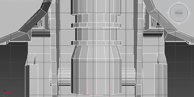
 The first issue became apparent when I tried to use the box projection tool. The chimney is a simple cylinder shape but is too complex for the box option to layout all the polygons correctly.


Having first tried the planar option on the vertical polygons, I noticed it result in the shape of the outer circle. This was useful for the top and bottom faces and hence I chose this option. After experimenting it seemed the most intuitive and effective solution for the vertical parts was the cylinder projection.


The process for the walls of the house was much simpler, simply requiring a planar projection for the flat, equal sized four polygons. It was made easier by the fact I could unwrap the roof as one square as it creates a flat projection.


After adding a simple tile texture made in Photoshop, this is the finished result shown in perspective view:


Good parts:
  • All parts except the chimney are represented by a simple rectangle shape on the uv making it easy to work with 
  • The chimney and the house were kept separate to easily apply different UV maps to the different shapes
  • Having the chimney as a different UV map means it can be larger to have more detail

Improvements:
  •  As can be seen on the chimney, grey marks can be shown where the seems are meeting. A seamless texture will likely improve this issue
  • The lack of a seamless texture is rather noticeable on the roof where the corners meet

Friday, 13 November 2015

Bibliography

References

Ross, Aaron F. '3Ds Max 2015 Essential Training | Lynda.Com Training'. Lynda.com - A LinkedIn Company. N.p., 2015. Web. 13 Nov. 2015.

Ross, Aaron F. 'Opening The Material Editor From The Course 3Ds Max 2013 Essential Training'. Lynda.com - A LinkedIn Company. N.p., 2015. Web. 13 Nov. 2015.

Final Evaluation

This final post is a reflection on the end result of my three models with evaluation of each. I have ordered them according to my opinion of their quality with the best first.

R2D2


Comment: I believe this is my strongest model and am very pleased with its outcome. I was able to add in the vast majority of details and all have turned out neatly and with the desired appearance.

Improvements: A clearer definition between the head and the body beyond different colours would have benefited the model. Though efficient and with a good appearance due the inset, creating the panels on the body in texturing or as separate object would significantly reduce the edges and hence poly count.

Prominent Issues/Solutions: The biggest issue with R2D2 was creating the head panels. Having them as separate objects to give them depth meant fitting them to the rounded surface of the head. Though time consuming, the solution was to duplicate and scale up the head and cut out the shape of the panels.

Accuracy and realism: Of all the three models, I believe R2D2 was the most accurate to the technical drawing and the actual character from the film. Details ranging from wheels on the feet to the various panels create an overall realism in terms of matching the film.

Snowspeeder


Comment: Due to the initial issues I faced in creating the complex shape, this model is a close second to R2D2 because of how successful it turned out upon competition. While inherently less detailed than the previous, the final result has the desired appearance with the details not being too difficult to achieve. 

Improvements: The main improvement to this model would be more surface detail on the wing. While texturing will provide a worn metal effect for variation, the slight engravings on the version from the film make for a more interesting appearance. The plain surface makes it stand out as lacking in some detail, especially as the setting for the animation is a snowy planet of a similar colour.


Prominent Issues/Solutions: As discussed in the primitive shapes diary update, achieving the shape proved the biggest issue for this model. This compounds another issue of relying too heavily on the technical drawing for reference as it was necessary to model the thin wings first for the solution. By making the wings first, the cockpit and bottom shape were easier to extrude out and create a more realistic shape with.

Accuracy and realism: While lacking in some of the surface detail, the model does offer some specific elements such as the backward 'z' found on the film version. Having taken a long time with the model to perfect the unique shape, I believe this also aids in the realism of the model which will hopefully pay off in the snowy setting of the storyboard. 

AT-AT


Comment: While in comparison the AT-AT does not stand out as a highly detailed model, the main body alone shows careful attention to various surface details as in the film version. I feel the model has successfully captured the unique appearance of this unit; the shape is very different to even the ships and droids found in the same scene on the snowy planet of Hoth my scene is based on.

Improvements: The model would benefit from a better solution to adding the inset details such as on the middle of the body. Such panels require some some connection to the edge they are surrounded by, and this can create a messy appearance when looking in edged faces and make the shadows act in an undesirable manner.


Prominent Issues/Solutions: Due to a lack of top or bottom technical drawings, it was difficult to tell how the legs were connected and what detail was found on the underside of the main body. Researching online revealed the shape of the axis which connects the top of the legs and I was able to create it by referencing that

Accuracy and realism: While this model does not offer as much realism as the others and feels more low poly, the details on the body and legs in particular do accurately match most of those found in various images of other models, the film itself or promotional images of the vehicle.

ATAT Progress Diary #2: Details


AT-AT

The AT-AT is an interesting model in the sense that it has both a relatively simple base shape but also much detail. Using reference images helped with positioning but more often than not understanding the detail of the shape was useful from online research of different perspectives. 


The head featured some complex extrusions which required more than the connection tool could offer. In some cases it was necessary to manually align to moved vertices to achieve the desired shape or simply line them up. The tool is however a quick method of creating extra surface geometry when combined with the 'insert vertex' tool.


As proved by both the previous methods, creating surface detail and unique shapes is most effectively achieved through the connect and boolean subtraction tool. These have have worked well time and time again because they allow unique shapes to be cut out such as the tube shown connecting the foot and the 'ankle'. Removing any intersecting geometry is good practice and avoids issues of clipping or wasted contribution towards the poly count.


The details on the side caused an issue in debating the best method for adding these shapes. While using autrogrid on the boxes on the top was ideal, the panels shown in the middle had to be cut into the shape. While fairly quick and easy to do using boolean subtraction, adding a lone box with no connections to the face it is in can cause issues with the shading and rendering by adding extra necessary edges. This is not always an issue, but as in this example it appears to occur more frequently on more complex and uneven surfaces such as this.


 While the reference images offer many benefits in terms of accuracy of details and keeping proportion, they are limited in what they can show. Researching different views online revealed how the legs were connected under the main body. Using 'inset' and extrude on a cylinder created a unique shape with much detail and only edges where they were needed. I chose to keep the default 18 edges of the cylinder as this is a large shape and a more low poly appearance would stand out more. Smaller detail such as small guns have less segments.


The model with all it's details is shown below in all viewports and perspective view. I have enabled edged faces to help the detail stand out better, however texturing and ambient occlusion will achieve this for the second assignment.


 Good parts:
  • High level of detail in important areas that will be focused on in the animation sequence
  • Unique shapes made possible through effective use of boolean subtraction
  • Attention to detail in areas such as the foot connection having a cylinder go through the foot to link them
  • Good practice including using boolean subtraction to remove intersecting geometry 
  • Detail included in modeling and not texturing gives it depth such as using inset for panels and windows for the slight surrounding gap
Improvements:
  • Better solution for cutting out panels to avoid adding extra edges in undesirable places 
  • Areas such as the neck are polygon intensive to created bumps in the cylinder. An extended primitive may prove a better a solution
  • High level of detail has resulted in a high poly count. While this isn't too intensive for rendering the animation, exporting the model to a game engine would likely require some simplifying

Thursday, 12 November 2015

Snowspeeder progress diary #2: Details

Snowspeeder

The details on the snowspeeder proved an interesting challenge due to its complex shape. Where possible, making details such as the gun support a separate object made them easier to create and kept the position and angle of the sloped wing. 

The biggest difficulty I faced in adding these details was with the windows. The sides of the cock pit are both sloped but also scaled in at the front to create the elongated rhombus shape on the top. This meant using the 'connect' tool would not produce a straight line and manually moving the vertices would change the shape. The solution I used was to make the cockpit an even height on the top and use the 'swift loop' tool which created a much more even edge round the shape. A downside of this is of course the resulting excess edges of which only some can be removed so as to maintain the shape as shown below.                                                                                   
  

As mentioned above, keeping the gun supports as a different object had many benefits. Without affecting the surface geometry of the main body, I was able to inset and extrude the top edges, created inset panels and the grills shown on the front using 'connect'. These frequently used tools have proved the most effective and intuitive for creating these parts. Settings such as deciding exactly how many edges I wish to add make these tools the best solution for creating polygon efficient detail. Keeping this as a separate object did however have its complications. Neatly aligning it on the slope was difficult and using boolean subtraction to cut off any intersecting parts created some extra vertices to do so.


The flat surface of a component such as the front gun support makes adding detail a much simpler process. The 'autogrid' tool available when creating new shapes allowed me to make this cylinder sit perfectly on the surface of the support.


 The tool also worked well on the sloped surface of the back of the main body. This backward 'z' detail was quickly created using the text tool. Being under the same section, I realised the same techniques used in extruding a spline shape could be used to give this some depth. Mirroring the geometry with the default central pivot point quickly flipped round the standard 'z' shape. The mirror tool was also useful in copying this to the other side, but did however require aligning its pivot point to the centre of the snowspeeder. This would mean I would need to change the pivot point back to make changes and repeat the process to mirror again.

 
The 'grill' design of the engine was achieved by extruding out of the flat surface of the back of the main body. While the connect tool was efficient on this surface, it proves that the tool though working as intended is limited by the edge's positions. As always, the central detail was created with a separate object used to cut out the shape, but only as a reference so it would not be deleted. Removing hidden parts such as this will avoid any potential clipping issues. The leg supports were added toward the end for the purposes of a realistic and accurate model.


 As practiced in my R2D2 model, the inset tool can be used to created the fan effect shown in the central circle. Having the faces pulled in each time it is used makes for easy selection of alternate ones to extrude, but is quite polygon intensive for a relatively small detail.


As discussed in the primitive shapes discussion, the flat bottom side of the main body lacked realistic detail and shaping. Researching images of the bottom, it became apparent there was a elongated rhombus shape much like the cockpit. Using the connect tool and manual manipulation of vertices, I was able to add this geometry to the model. While this is not an obvious place and is likely to not have a direct shot looking at, it does add to the overall accuracy of the model and can be partially seen from the side view


Good parts:
  • Attention to detail on complex shape and realistic parts such as leg supports
  • Multi/sub object texturing helps panels stand out
  • Use of new and interesting shapes such as the text feature
  • Slight gap around panels to better highlight them when rendered
Improvements:
  • Window shape is not perfectly positioned due to abstract shape of cockpit
  • The model would benefit from slight engravings on the wings for added detail


Wednesday, 11 November 2015

R2D2 Progress Diary #2: Details


Details

With the primitives complete, I started to to add the many surface details of R2D2. It became apparent there would be many different shapes and edits to do and for each I decided the best solution based on past experience with exercises.

Head


The main detail on R2's head are the blue panels. Having decided to use a sphere for quite a lot of detail, this proved beneficial in having ows of columns following the natural curvature of his head. Cloning the appropriate polygons, scaling them in and cutting out the different panels was made easier by the swift loop and connect tools for adding more edges. While it may have been easier to inset and extrude the appropriate panels, having the panels as a separate object allowed them to stick out more and meant the sphere could keep it's neat polygon structure.


Unlike the head panels, most of R2's body details shown in white made more sense to be modeled on the body object. By combining the inset and extrude tools all the panels catch the light more clearly - similar to the slight outline between beveled keys on a keyboard. As covered in one of the earlier video tutorials, the bend tool proved useful for the complex blue panels at the top. While it doesn't perfectly match the curve of the body, bending the shape before cutting into the object left a better impression and allowed the subsequent extruded object shape to stand out more. Simple multi/sub object texturing helps discern each object but will be improved upon for the second assignment. 


An incredibly useful technique covered in the lectures sped up the process of making the cables for the feet significantly. While initially I may have tried to edit a sliced torus, using a thickened, rendered spline and editing in all 3 axis' created the perfect effect that was easily manipulated. When scaling out the connecting silver socket it did however require the tools of an editable poly which lost the easy and neat manipulation of the cable. Moving and rotating the end face allowed me to do this, but with less freedom than the previous method. 

While the legs and feet were modeled as separate objects, towards the end I noticed they needed some form of connection. After researching many images from different angles, I concluded that a rhombus shape is cut into and uses a half a cylinder to pivot the foots rotation on. Adding this shape in later proved more difficult with aligning but was still possible, and created a more realistic and accurate appearance. 


The two most useful tools for creating the leg were boolean subtraction and extruding splines. Using the reference image, the top hinge was quickly created by combing an arc and a line with the fuse and weld vertex tools. While shapes like this can add a number of polygons, efficiency in other areas such as removing height segments or less sides on a smaller cylinder makes up for this. Boolean subtraction allowed the central tubes to appear they were coming out of the blue panel by cutting it half way down.


Good parts:
  •  Where possible, unnecessary polygons have been removed to allow for necessary detail in other places
  • Parts such as the cabling show unique shapes and tools not used in previous exercises 
  • Most details of R2D2 have been modeled, including some not obvious in the reference image
  • Use of reference images for keeping proportions and positioning of details as much as possible

Improvements:
  •  Appearance in viewports sometime supersedes the reference image e.g. the angle of the eyes on the head. Could benefit from a better reference image with a top view
  • High poly count from some necessary details. If exporting for use in a game the model would benefit from less detail in areas that won't often be seen in game play such as the sides

Sunday, 8 November 2015

3DS Max Tips #4, peer review and own research

Lynda 2013 (Ross, 2013)

Compact Material Editor

  • M key to open material editor
  • Can change perview object 
  • Middle mouse click to rotate preview
  • Map is applied to a parameter of material e.g. its colour
  • Can drag sample slot onto object
  • Only 24 slots available, recycle by using get material and select standard, this will not affect anything in the scene 
  • Two materials of the same name can be changed between in the scene while keeping both types of materials 
  • Eyedropper tool useful for grabbing existent colours
  • Architectural gives simpler properties menu with useful presets for different real life materials like glass 
  • Specular high glossiness means lower spread - lower spec level and glossiness creates strong highlights
  • ActiveShade allows changes to be made while previewing final rendering - Perspective > Extended viewports > ActiveShade - any movement needs to be 're-initialised
  • Turning down opacity does not bend or refract light, to do so go to Maps > Refraction channel > Select materials - in this case raytrace 
  • Go to parent goes up on level of what has been edited


  • Slate Material Editor


    Slate material editor is newer version
  • Double click node to see parameters in similar view to the compact mode
  • Changing shader loses parameters and colours
  • Architectural and standard look much the same, standard gives more freedom
  • Drag output circle on to object in scene
  • Deleting nodes doesn't not necessarily delete it in the scene, drag back from scene materials - instance is version in scene, copy would be a new version
  • Deleting something not assigned gets rid of it forever, needs to be saved in sample slot
  • Tools menu option allows you to minimise some menus and tabs
  • Less diffuse means stronger specular highlights 
  • Realistic and illuminate with scene lights shows better idea of what it will finally look like
  • 150 for strong specular level is good, lower glossines makes it more focused, soften changes back light intensity 
  • Anisotropic lighting is good for hair - 'not the same in all directions'
  • More than one material on one object - create two separate materials, assign main material and apply, then select individual polygons and drag material on
  • Another method is to drag on a multi sub-object, create materials and assign in different slots on properties menu. Using first method, it will inherit the polygon selection and swap out the colours
  • Can change ID in modify tab, properties of multi sub object corresponds to this

    Peer Review

  • Initial thoughts - Joeseph has clearly thought about the universe and has a clear view of what he wants to replicate in his project. Reference images and even a 'GIF' aids this
  • Look and feel - Including the inspiration both from anecdotes and images in the moodboard are useful to keep focus and to demonstrate his vision to the marker
  • Storyboard - The models chosen are complex enough but still realistic. The sequence is not too animation heavy and will likely require minimal rigging. This is important as learning toward the end of the assignment that the animation is too complex would cause big problems
  • Pirate wheel - Joseph has shown this particular exercise and shows an understanding of the tools needed to create certain effects that may also be useful in his final models  
  • Sandcrawler - The sandcrawler is shown at different stages, first with it's base shape and then the detail in the back. This is effective as it shows his process but also allows for any issues and solutions to be documented 
  • Research (Comic Con) - This unique post shows he has gone beyond the week's content requirements and is using real world examples for inspiration and reference 
  • BB-8  - The simplicity of the model has allowed for more time to be spent on the other two. It is likely the detail will be more prominent when it comes to texturing with this choice of model
  • R524 - The different components of the model such as the leg are discussed in terms of the process without detailing each tiny component. This demonstrates he is conscious of the model at each stage
  • Improvements/final thoughts: The blog could benefit from more detail and evaluation of exercises but portrays a clear understand and vision of the end result with evidence of realistic, detailed models

Own Research

  • Slice On: When creating primitives such as spheres, it is likely a hemisphere will be needed at some point. This property allows you to cut the object to and from a certain angle to create a hemisphere in any desired direction. This is useful as it saves on time compared to other methods such boolean subtraction to half a sphere
  • Ctrl Backspace: When removing lines, the remove button is handy to safely delete the edge without removing the whole face. This doesn't however removed the lingering vertices. Using control back space on edges or vertices will remove both. This tool must be used carefully though as if an edge is necessary to main the shape it is connected to, this will either not work or could delete the whole face. Depending on how the model has been edit, it can also make sloped edges lose their definition.
  • Imprint: Used either with primitive shapes or a spline drawing, leaving an imprint in the same way you would subtract can be useful for creating surface detail that needs the edges defined on the face. Found under the boolean tools, this tool will likely be useful for R2D2's many panels. It does however create added edges if necessary so the shape has something to connect to.

Saturday, 7 November 2015

3DS Max Exercises #4.2 - UVW Mapping, Cloud Procedural Map

UV Mapping 
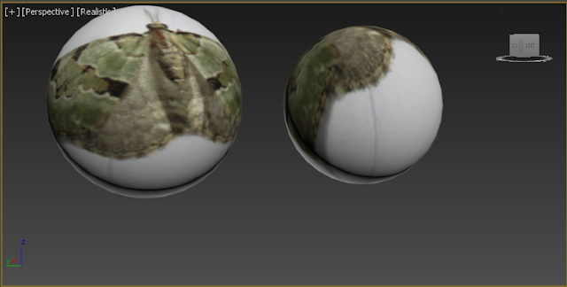
As discussed in the previous exercise, simply applying a 2D image to a 3d object can cause issues. The UV mapping tool allows the textures to be projected from different source shapes. Following the notes, I have applied the moth texture to different shapes:
The box projection has resulted in the image being being projected onto every side separately. The image fits perfectly on each face due to the projection box being the exact shape of the object. This will be useful on the main body of the AT-AT as this is made of up flat faces as part of one large box.


The left sphere uses a spherical projection shape. This option has projected it as though it was a flat surface of a box but of course this has resulted in the image bending round the sides. If the white section is turned transparent, this may bw useful to make the wings appear they have moved for an idle prop. The 'shrink wrap' tool has taken the two sides of the texture and made them meet at the bottom resulting in the moth being stretched around the top. This is not useful for the moth but would work with a seamless texture such as the metal surface of R2D2's head. 
   

The result on both cylinders is the same on the height segments; the moth texture wraps around and meets back at the starting edge. With the 'cap' option selected the texture has been applied on the flat surface similar to the result of a box or 'planar' projection. This may prove useful for the cylindrical guns on the snowspeeder and has the flexibility to apply the texture to the end of the barrel if needed.   


The face projection option has tiled the image on the surface in the same manner as the checker material did in the previous exercise. While potentially useful on the main section of the teapot - and indeed any complex shapes on my models that needs a seemless texture -the same issues as before arise with stretching on the spout. 


To create the effect shown in the notes of the moth over the top and sides I looked at previous results on primitive shapes. The sphere option seemed most appropriate as the moth wings do not touch at the bottom. The more complex the same, it is evident the more stretching will occur however.


Offseting a box shape for projection worked best for applying the texture on opposite sides with minimal bleeding. While this mostly works on the sides, the image is applied to the complex parts like the spout and handle and the face behind them resulting in a strange and undesirable result.


The images below show the result of combing procedural maps to create a cloud effect. Using a combination of preset materials and tweaking settings to create variation, a realistic cloud effect has been created. The step concerning render settings has also taught me about setting background colour which will be useful for the snowy atmosphere of Hoth - the planet my scene is set on. I created a pyramid on a sandy plane for contrast.


Review of clouds
Good parts:
  •  Transparency adds to detail and quality and allows the detail to be seen when looking down, and the sky when looking up
  • Uses a combination of preset maps and hence does not require artistic skill to make
  • Many settings allow for variation in spacing and size and makes a for a realistic appearance
  • By simply changing the background colour to blue, a realistic sky has been created with the clouds
Issues:
  • Requires a lot of scaling up to cover field of view, though this may be solved by using a different type of camera or technique 
  • Long process to create extra detail for the scene but can be used in any scene once made by importing
 

3DS Max Excerice 4.1 - Materials


Materials
The slate material editor in 3DS Max provides a quick way of applying more than basic colours. The following exercises demonstrates small but effective details that really help the quality of the model.
To create a metal effect, I first made a sphere as I feel this shows the most lighting of all the primitive shapes. When playing with the settings, I ended up with a high glossiness level to increase the spread, and a higher specular level with the graph going to the top for more intensity than spread.


To create a wood effect, I had minimal glossiness and a medium level of specular intensity so there would be a subtle shiny spot but not all over.


The exercise to apply a checker material to different types of primitives proved useful to see how a 2d image fits to different 3d shapes and surfaces. The two main issues of applying a 2d texture on without unwrapping the model are stretching as shown on the tea pot handle and different sides not lining up at the edges. For planes or texturing on the face of an object this would prove useful - it could be used for creating an 'in-scene' poster quickly.


The below image shows the result of experimenting with procedural maps. While all have the benefit of being seemless and not distorting even when change the shape of an image some seemed more immediately useful than others. With minimal tweaking I was able to generate textures for marble flooring, a smoke effect and freckled human skin (or the surface of an egg!)


Snowspeeder Progress Diary #1: Primitive Shapes

Snowspeeder

Having completed the primitives for two previous models in a fairly straight forward process, I first tried to make an outline of the shape using the spline object. I soon realised the snowspeeder was a complex shape and the reference images were somewhat misleading in terms of angles and positions of the different components. After finishing this first attempt at the main body of the ship, it became apparent that the object was out of proportion, especially in the side and perspective view. 


After finding a new set of reference images, I decided to take a new approach. Rather than having modeling an almost pyramid shaped object, I decided to model the outline of the cockpit and wings at the thickness of the wings. This allowed me to then extrude the cockpit add and some edges to the bottom to give it some body under the wings. This approach created a much more accurate look but took much longer to tweak. Keeping in mind the above issue I positioned the cockpit a bit lower than the reference image and I believe this has kept the model in better proportion with itself.  


When creating the gun supports, I was torn between different methods. From previous exercises I thought about using the spline tool with autogrid, creating extra edges and vertices with the connect tool or simply creating a new box primitive, shaping it and the using boolean subtraction to fit it perfectly. The auto grid method would not sit perfectly on the angled surface of the wing and adding the connect tool would require inserting vertices and assuring they lined up perfectly using the transform type in. Boolean subtractrion using a new shape made to intersect the wing allowed me to delete the element below the intersection and leave the support positioned and angled correctly on the wing.


The guns were modeled quite effectively from extruding the front face of a  cylinder. In some cases, the inset and extrude tools were used to create the thicker rings. This part of the model is probably the most polygon intensive, but the detail pays off and the rest of the models relatively low poly count allows for this.


The grappling gun was made up of different primitives except for the detail between the turrets. This detail was created by inserting edges using the connect tool. I chose to use this method rather than adding a number of segments at the start as the division was only needed on one face and this reduces polygon count contribution. Any holes created when deleting parts were filled using 'cap holes', a modifier requiring an editable mesh. Converting to editable mesh could be problematic so I only use this tool when bridging will not work and make sure to convert back to editable poly at the end. 


The progress so far is shown below in all views and in grey - the base colour of the ship.


Good parts:
  • Low poly body of ship allows for more detail on the gun 
  • Gun and body are separate groups allowing for easy movement of multiple objects
  • Body is split into different parts (support, main body) within the group so can be manipulated and have separate textured applied easier
Improvements: 
  • Doesn't perfectly match reference image; the model may benefit from using a better reference image that doesn't make it appear too elongated 
  • While the gun has good detail, it's polygons can be quite clearly seen and could do with more segments to create a more rounded appearance
  • The cockpit could be a separate object to make applying different textures for the windows easier