Thursday, 29 October 2015

3DS Max Tips #3, peer review and own research

Lynda (Ross, 2015) 
Polygon modeling
  • Graphite ribbon requires editable poly and modify mode
  • Toggle command panel keeps them hidden and always in modify mode
  • 1 vertex, 2 edges, 3 border (edges of gaps), 4 polygon, 5 element and 6 back to object mode
  • Sub-objects and ignore backfacing can be used to select whole shapes within shapes
  • Tools are destructive, there is no modifier stack - can only ctrl-z to undo
  • Use pivot point centre - fly out brings up other options such as selection centre
  • Ctrl backspace removes selected edge and associated vertex
  • quick slice can create edge loops over non quadrilateral shapes  
  • S for 3d snapping - use to create neat edge loop which can then be moved
  • with top view, selection rectangle can select a vertex and any directly under it
  • Soft selection requires no current selection, then make selection - creates heat map of how much you're affecting something with scale for example
  • Fall off affects area of influence 
  • Add tiny details at tend of work flow
  • Use chamfer to make edges less sharp
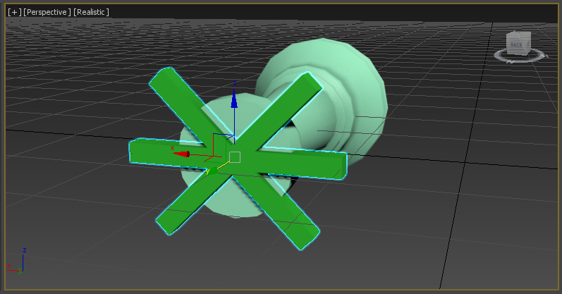
  • To modify the shape of cylinder to make it like a tear, use paint mode which is a fly out of the box select options - right click button and turn down paint brush size - select 3 vertical strips of polygons at front, with fall out the shape is distorted correctly
  • Bridge - bridging borders is best for gaps between - cleaner if lined up with same number of vertices along borders
  •  
    Spline modeling

  • Bezier curve creates smooth line
  • Change vertex type to bezier, corner etc
  • Disable transform gizmo by going to user preferences, gizmo, transform gizmos on or control shift f5-8
  • View drop drop down shows current constraints in effect
  • Delete to remove vertex, refine to add
  • Create line to add one, can hover of the vertex on the spline object and automatically welds to others
  • A drawn arc can snap mid drawing using s hotkey
  • automatic welding setting in vertex mode
  • Outline tool on spline to drag out thickness
  • To remove detail where it is not needed, interpolation setting to decrease number of segments between lines and converting to corner or other modes where relevant e.g. two corners for square base of bell
Review of fellow students work

Joe Hall

Look, feel and storyboard post: 
  • The analysis of the Star Wars 'look' is sophisticated, with a comparison to Star Trek to clearly demonstrate what he is and isn't going for
  • The 'Feel' description looks at the story and context of the star Wars universe - this is good reference material 
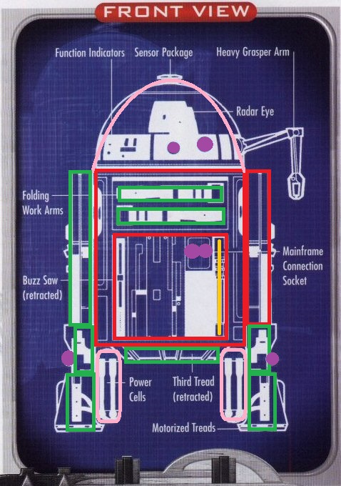
  • The chosen 'Trench Run' sequence is achievable; the chosen ships and landscape are not too complex and the scene and ships are well documented for reference
Wheel, house and castle post: 
  • Ship wheel: Joe mentions the design process and what tools he found useful rather than a step by step process of what happens
  • House: A good description of the house is given as he talks about using new tools and fixing issue created by the method (e.g. filling in gaps of deleted polygons)
  • Castle: He talks about the best way he could do the arch at this stage, and how he could improve it in the future with tools he has touched on                                                                                            
Low poly house: The low poly house shows and improvement in detail still using mostly the same techniques

Own research

Chamfer: This tool has allowed me to create rounded corners on shapes. This has proved quicker and more flexible than drawing a spline outline with a curve. Both methods would inevitably create more polygons for a relatively small detail however so must be used sparingly
   
Cap holes: Where holes have been created from deleting vertices, a tool for filling the gaps rather than adding geometry is very useful. While I have only used it to fill holes when deleting windows in one method of the house exercise, with more complex shapes I believe tool will become useful. One potential issue is the need for the object to be a editable mesh, as most editing needs to be done editable poly and this also recommended for exporting


Extended primitives: While most shapes under the standard list cover most requirements and can be edited otherwise, some more complex and less used shapes are available under the 'extended' list. Objects such as 'hose' will be useful for the AT-AT neck, however after using it I found this to be very polygon intensive

Sunday, 25 October 2015

3DS Max Excerice 3.2 - 3 View Editing plane

Plane

This exercise was useful in practicing and evaluating the method of three view editing when creating an object. If the reference images can be easily stretched to be all the same size with minimum distortion, this seems the best method for creating models with more accurate detail and realistic proportion.

Having the images the same size in pixels translated well when I put the same figures in 3DS Max despite being in a different unit measurement. This worked well with the align tool and created a virtual studio for the details and proportions. 


While options such as drawing over the reference image with a spline may get most of the shape, the method of blocking it out with primitives allows for much more flexibility in editing of their equally spaced faces. I used this to add the wing. This does however make it harder to accurately match the shape as you can only move and scale the faces given. 


To save time, I decided to experiment with mirroring the object. I decided to half the object and the copy an 'instance'. This feature allowed me to make edits to one side and have them apply to the copied side. This of course left me with two separate objects requiring me to simply attach them together.


The final result is shown below with all four different views and the 'virtual studio' of the reference images.


Good parts:

  • Correct and consistent proportions in each view has achieved a good result in perspective view
  • The model is perfectly symmetrical using mirroring and the 'instance' feature
  • The use of one extruded primitive helps to maintain a low poly count

Issues:
  • The method requires the model to have a technical drawing available. While in a studio context an artist could produce these, the more abstract the item the less likely there will be such drawings available online for an individual
Improvements: 
  • Some parts could be smoother using modifiers rather than the point pulling used here
  • More detail could be applied using extra primitives

Friday, 23 October 2015

3DS Exercise 3.1: Chess pieces

Chess piecesTo further explore the use of the splines, I completed an exercise in creating chess pieces from a reference image. The results and brief process for future reference are shown below. I created a pawn, bishop and rook. Each 2D objects was turned into 3D using the lathe tool that extended the shape 360 degrees around its centre.

Pawn

To begin, I used the spline tool to draw over the rough shape of a pawn. This resulted in quite sharp corners over the curved parts. To smooth them out, I used the 'fillet tool' which rounds the edge out by adding extra vertices around the selected one.


On this particularly large edge, I used the 'refine' tool which allowed me to add in extra vertices to make it smoother.


Bishop


The process for creating the bishop was identical to the pawn. To create the slit at the top, I created a square that I lined up with the reference image after hiding the bishop object. The square shape was then subtracted using the 'proboolean' tool.

 Rook

As before, the rook was created by extending the 2d shape of half of the object with the 'lathe' tool on the 'y' axis. Similarly to the bishop, the battlements were creating using boolean subtraction. The align tool was used for this model to centre the cross shape and have it accurately postioned on the top surface of the rook.


The final result is shown below in 'realistic' shading for all three model


Good parts:

  •  A detailed and realistic appearance for each piece was created from a simple and rough 2D outline of the shape
  • The process of turning the 2D shape into 3D using the 'lathe tool is fast and means any symmetrical shape with a reference image can use the same method
  • Using the 'fillet' tool resulted in smooth edges that translated well to 3D. This would take longer and be harder to achieve when doing conventional polygon modelling

Issues:
  • When using the '2D Pan View Mode' to align the objects with the background image, the result of the 'lathe' modifier' was a strange shape that did not extend the object correctly. This was solved by moving the reference image over to a plane, rotating that to sit flat on the grid and work on the models top down. This solution is evident from the second screenshot.
Improvements:
  • Both the rook and bishop have a pointy top. This could be improved by assuring the top of the outline is smoothed out more
  • The top of the rook would look more accurate if the battlements were thin rather than having a cheese wedge appearance from the cut out cross shape 
  • The process is quite polygon intensive as edges are created for each vertex used to define the detail in the 2d shape

3DS Max Tips #2 and lecture techniques

Lynda (Ross, 2015)

Basics and Interface

  • For reference images use a plane as this is resizable, the grid is not
  • Transform type in on bottom toolbar can be used to perfectly centre an object
  • Image ratio needs to maintained (if width is double the height, keep this height even if different to the exact picture size) on reference image
  • Keep images in sceneassets/image to maintain internal links
  • Under self-illumination, turn up to 100 so the reference image won't be affected by lighting
  • +, viewport configuration, improve texture quality if image is blurry
  • Lock image by click object properties, turn show frozen in gray off and interactivity- freeze on
  • Go to modify tab to see height, move down by half it's height to centre accurately through grid
  • Keep same value on Y axis if lining objects up in that axis
  • Customise, Configure columns on scene explorer to display colour, frozen items etc
  • If the number of segments was not set, go back to 'box' in modifier hierarchy and change it, then go back to other effects to re-apply them
  • Bottom to top dataflow, apply modifiers in this order
  • Light bulb on modifiers tab turns their display off
  • To collapse modifier stack and apply the changes to an explicit object, right click top modifier and collapse all - save version with modifier stack and version with collapsed
Lecture techniques

  • Adding vertices - Adding vertices along an edge has proven useful where surface detail needs to be added. While 'connect' has the advantage of equal spacing when creating extra edge for example, adding vertices allows for the flexibility of placing them anywhere along an edge. I did however encounter a problem when using this as lining up the two vertices to create a perfectly straight line is very difficult. The snapping tools used so far have do not allow incremental mouse movement withing and edge that has no vertices.
                      
  • Connect - if two vertices needed an edge between them or even two edges being equally divided, the connect tool allowed this to happen. This also useful as it allows only the edges needed to be added rather than using the segment settings on the primitive object. It also has the added benefit of accurate spacing of the lines and an option to slide them along too. This is particularly useful if only one line is created and it needs to be positioned somewhere other than the centre it defaults to. When creating the low poly house, the connect tool caused an issue with creating the window bars. Once the vertical lines were created, the horizontal ones could no longer be as the clear path from the two edges being connected was blocked. This was solved by creating lines from each edge to the vertical bars, and then going into vertex mode to connect the central box of vertices.
  • Boolean operations - as proven in the first house exercise, using boolean operations to subtract one shape from another proved the most efficient for creating window holes without showing the hollowness inside of the object. The 'union' tool was also useful for merging objects into one, such as the floor of the church in the derelict village which is made up of three different planes. The main issue I have encountered is the pattern a complex shape will leave. For example, to cut a simple circle shape, faces for each of the 18 sides of a cylinder will be added to the shape. This is particularly damaging to the poly count when using a sphere as this has many faces to achieve its round shape. The solution to this issue is to be selective with the tool to make sure the poly count is only added to when no other method would work.
  • Grouping - Grouping will become increasingly useful as my models increase in complexity. While it may seem neater to just merge all objects into one, it is inevitable that certain parts of the model will need editing individually. In the context of a star wars ship, this could mean grouping the different parts of the wing while keeping them, and the overall wing, a separate selection from other parts of the ship. Ungrouping retains any sub-groups which may be useful.
  • Aligning - Aligning is an important tool for accurate positioning. With a combination of lining up the maximum of one and the minimum of another on the z axis and the centres on the x and y, objects can be quickly positioned exactly where they are needed. Issues arise when trying to do all three axis at once, so to understand what is going on and achieve the best result it is best to do it one axis at a time
  • Splines and lofting - When creating complex building shapes, the spline tool has proved much more efficient than combing many primitives. Being able to draw out the shape of the inner and outer walls then extrude them up has enabled me to create more interesting shapes of buildings, such as the church in the derelict village. An immediate issue with this methods is that no floor is created when extruding the walls. This is easily solved by first converting the inner spline to an edible poly (which fills it) and then copying that shape.
Own research

  • Import - As shown in the broken cart model in the derelict village exercise, importing previous work is possible in 3DS Max. While it is unlikely for the assignment I will need to import a whole model to another project file, this tool is perfect for copying over things such as intricate decal or generic parts such as wheels or guns. Combining this with the align tool proved a quick way to add the wheels on to the cart and hence this a useful method I aim to use in the final models if appropriate.
  • Bridge - If two edges leave a gap where a face should be, I found the bridge tool to be quite useful. An example where this might happen is when deleting faces to make a door which exposes the hollowness inside of an object. Using bridge on the edges will fill in the gap. As show below, it can also work between two separate elements if attached.


Monday, 19 October 2015

3DS Exercise 2.2 Derelict village

Derelict village

Using the techniques I have learned so far, I have created a derelict village suitable for a game. While set in a typical fantasy setting, the village is still suitable for an FPS. It features multi story buildings such as taverns and churches to enter. Holes and broken parts cover the buildings for the practical purpose of shooting from cover as well as for aesthetics and setting. The below images show a top down and front view of each building.


I first added my top down sketch as a material to the image plane. While only a rough guide for positioning, this is useful to keep proportions and spacing between buildings.

Tavern and stables
The first building is the tavern and the attached stables. Created by extruding a 2D spline, the building is a 'L' shape. The fence on the side gives it the 'derelict' look by simply rotating some of the posts to appear near-broken. The hay barrels are useful props for suggesting the purpose of the fence (as a stable), but would also allow a player to climb and jump onto the building from in an FPS context.
 

I also experimented with the text tool to create a swinging sign; the 'autogrid' tool allowed me to position the lettering accurately on the sign.


The interior features broken tables and a bar stool. Both give reasonable cover if needed in a FPS context. The 'autogrid' was once again useful for accurate placing of the legs on the table.


Good parts: 
  • Interior with corners and props could be used for hiding if used as a FPS map
  • Broken door and props break up the otherwise simplistic geometry
  • Simplistic shape of building does not give a high poly count contribution  
     
Issues:
  • Extruding splines leaves a hole where the roof should be, meaning multiple planes (to match L shape) needed to be created and attached, adding to the poly count 
Improvements:
  •  A more interesting outline shape would make the geometry less repetitive and bland. Curved shapes could still be achieved with the 'bezier' spline option
Broken Cart

While this isn't a building, the broken cart is a large prop that immediately gives the impression that the village is war-torn. I imported the ship wheel from a previous exercise to save time and used them as the cart's wheels. 

Good parts:
  • Imported wheels saved time in creating the large village
  • By using the same wheel object simply laid on the floor the cart has a broken appearance without modifying any main geometry 
  • Cart was created by subtracting a scaled down copy of the box rather than adding extra segments just to cut out the shape
 Issues:
  • Aligning the wheels to the main cart gave a good starting position though still required some tweaking - the wheels are not perfectly lined up
 Improvements:  
  • An axis for each pair of wheels would give the model a more realistic appearance
  • A more damaged appearance could be achieved by editing some of the vertices or cutting out some shapes, though this would add extra polygons for a small detail
Watchtower

The watchtower is the second building to include an interior. It features a small window slit for shooting out of and a ladder to the top surface. The shape was modeled out of one large cone with the top face scaled in.


Good parts: 
  • One primitive shape with removed height segments maintains a low poly count contribution. Changes such as scaling in the top do not add to this
  •  Windows slits were achieved by simply cutting away a box shape, not requiring any extra surface polygons to delete the window shape
 Improvements:  
  • A spiral staircase would be more realistic and allow for more windows slots as players could stop at any height and shoot out of them
  • Battlements would distract from the appearance of the tower being one large shape and provide cover in a game 
House
The second object to be imported in, this low poly house was taken from the previous exercise. While it remains much the same, details of damaged walls have been added as seen on top of the second windows from the right. Creating a random shape with a spline, extruding it and using boolean subtraction allowed the wall shape to be kept while breaking away parts.
 

Good parts:
  • Imported model was able to maintain most of it's shape as changes only needed to be made to surface faces
  • The spline tool allowed irregular shapes to be cut out of the house rather than cubes or spheres
 Improvements:
  • Larger, more noticeable details such as a boulder hitting the house would improve the damaged appearance
  • If an interior was included, this could feature damaged furniture such as fireplaces or cooking fires 

Church

The final building of the village is the church. This is the main structure on the map and has the most places to hide in. The two story building features broken front doors, an altar and pews, a ladder and a second story with bed rolls.


Good parts:
  • The multistory building provides enough space to include more detail and props
  • From a game standpoint, the church could serve as a sanctuary or a defense point due to the two stories. The lack of windows and many props to take cover behind would work well in an FPS scenario
  • The align and clone tools allowed multiple props to be be lined up and repeated accurately   
 Issues:  
  • Due it's non-standard geometry after extruding splines and attaching floors, boolean subtraction caused issues with adding extra internal edges and polygons to make up for those lost
Improvements:
  • Breakable windows would break up the single shape and allow an enemy team better access to it in a game
  • Battlements or statues on the roof would provide another less obvious place for a character to reach and add interesting detail to the shape  

The final result is shown below in 'wireframe' and 'realistc' rendering:

Friday, 16 October 2015

3DS Max Exercise 2.1: Low Poly House

Low Poly House


This exercise allowed me to use my existing techniques and skills to create a higher detailed though still low poly house. It also allowed me to practice two new techniques called 'connect' and 'bevel'. While previously I documented steps in exercises for future reference of specific parts and, in the case of the house, to analyse each method to chose the best, this post will be more concerned with the evaluation of the result.This will be true of most of the exercises to follow, unless any important methods become noteworthy.

The edges shown here were achieved with the 'connect' tool. With two edges selected, the tool will create one or many lines at equal distances in between them. As shown in this close up of the window, I create two vertical edges using the tool and then changed the 'pinch' setting to bring them closer together. This is not however restricted to just edges, the square in the middle as shown below was achieved using the tool with vertices. Unlike the segments method of the first house exercise, this methods means only the polygons needed can be created.


The sloping on the top of the house was created using the 'bevel' tool. The height and outline size can was changed using the caddy to achieve the desired amount.


The roof was achieved by using the connect tool and moving individual vertices. These points were then moved up on the 'z' axis to create the raised roof. The finished result is shown below in 'wireframe' and realistic shading mode.  


Good parts:
  • More detail on windows by using 'connect' and 'extrude' for cross panels
  • 'Bevel' tool creates interesting geometry rather than a simple cube for a house
  • Various shapes and slopes on roof also create an interesting and more complex roof
  • Windows were created without needing to split the whole face into many equal polygons as in previous methods; the model is detailed while maintaining an effective poly count

Issues:
  • After using the 'bevel' modifier on the flat roof service, the front edges of the largest face became curved. The problem was avoided when those edges were dragged back to form the prism on the front two faces

Improvements:
  • Removing the window shape polygons or separating them as a different objects would allow them to be seen through. This could be achieved by applying a transparent texture to the separate object or explaining the gap as a broken window

Tuesday, 13 October 2015

3DS Tips #1 and further thoughts on models


Tips from Lynda 2015 tutorial (Ross, 2015)

Setup
  • Always set up the project folder correctly to maintain links (textures stored in different folders)
  • Download help documentation as internet is unreliable
  • Convert local files paths to relative - wont store entire path address, only what folder it is inside inside the project  - links will maintain if you rename or move 
UI
  • Drag off parts of the UI and close using the 'x' cancel button to get rid of them
  • Views - ViewCube - untick 'Show the ViewCube' if it gets in the way
  • Right clicking snap tools opens up grid and snap settings, increase perspective view grid extent to make the grid bigger
  • Grid colours - customise ui, drop down grids and change intensity 
Hotkeys
  • Alt middle mouse achieves the same effect as dragging the mouse around the view cube. Rotates around an object if one is selected
  • Alt W maximises selected view port
  • Tab and number keys allows the different axis to be cycled through and a specific number to be input when moving, rotating or scaling
  • W selects move object mode
  • E selects rotate object mode
  • R selects scale object mode
  • Q activates select object mode
  • Z to dolly in one object (like zoom but doesn't change field of view, just moves camera) 
  • F3 toggle between realistic and rendered
  • F4 enables edged faces - shows polygons on top of selected shading mode 
  • Shift Z will undo view port changes 
General
    • Objects should have uniform scale, change in parameters in modify tab not using scale tool
    • Right click move rotation or scale and a window to open pop up to type in transform values
    • Shaded mode reduces performances issue (no shadow or lighting)
    • Right click on menu bar to activate 'View ports layout menu' bar and use arrow to add a layout to the presets 
    • Creating objects to be used to cut away shapes can be moved and scaled accurately on the 'x' and 'y' axis, but must be moved by hand on the 'z' axis
    • Creating angled walls is easily achieved with 'bridge' tool
    • Vertex snapping when using autogrid on the surface of another object is the easiest mode to make sure the surface of the shape is fully matched
Further thoughts on models

Having completed a number of exercises and tutorials, I have returned to the design of my models. I have taken technical drawings for each and drawn over them the primitive shapes I plan to use. 


Drawings found at: http://starwars.wikia.com/wiki/Category:Technical_drawing_images


Drawings found at http://starwars.wikia.com/wiki/Category:Technical_drawing_images

http://starwars.wikia.com/wiki/Category:Technical_drawing_images


Key
  • Red: Cube
  • Green: Cube with edited geometry (e.g. extruded or moved faces for trapezium on AT-AT body)
  • Yellow: Cylinder(s)
  • Orange: Tubes (Halved with boolean subtraction for AT-AT horseshoe shape near foot)
  • Purple: Tubes/cylinders
  • Pink: Capsule

Saturday, 10 October 2015

3DS Max Exercises 1.3: Castle

Castle

Using the techniques I learned from making the house, I have made a low poly castle. First, I positioned the basic geometry using cubes. Rather than having a four square walls again, I wanted to have some angled corners. After playing around with different methods used before (such as boolean subtraction) I found the 'bridge' tool. This creates faces between those selected.


The result of using the 'bridge tool' between two equally spaced faces is shown below:


The remaining parts of the castle were relatively simple using techniques from the house exercise. The battlements were cut out with cubes using 'boolean subtraction'. I used the same method for the door, however explored the 'extended primitives' menu option to search for a capsule which, when placed half way through the grid, created an arched entrance effect. The inner keep was made from another object in the extended primitives menu called 'L-Ext' and has a similar arched entrance cut out of it. The watchtowers are simply cylinders; hidden polygons have been removed with boolean subtraction as before. 

The final result is shown in wireframe and 'realistic' rendering:  


Good parts:
  •  Using a capsule for the arched entrance created a realistic arch shape from only one object
  • Hidden polygons were able to be removed in the same way as the wheel and house for efficiency 
  • Grouping together cubes to cut out battlements were accurately positioned by grouping them together and moving them on the y axis
  • Interesting shape for inner keep was achieved from one object
Improvements:
  • More accurate placing of ramparts around corners 
  • Separate floor plane for inner ground and grass outside 

Friday, 9 October 2015

3DS Max Exercises 1.2 - House

House

The second exercise was to create a house. This must include four walls, a floor, a roof, a chimney and windows - two on the front and one for each side. I am going to try different methods of creating the window holes and evaluate the pros and cons of each.


Geometry modeled around window

The first stage of this method entailed modelling the house out of many different shaped cubes. To create the window holes I first positioned and scaled the cubes below and to the side of the holes. I then used a combination of the auto grid tool and changing the snap mode to 'vertex'. This enabled me to use the tall cubes to the side of the holes as the grid it was being placed on. Using vertex snapping, I created the top face of the cube above the window from the corners of the tall cubes and dragged it down from there.


Experimenting with the 'Hide Selection' tool, I was able to create the chimney. Having created a pyramid for the roof, I then hid it so I could accurately scale and position the chimney from the ceiling plane. After hiding it, I moved it up on the Y axis so it was slightly inside the pyramid and used the Boolean subtraction tool to remove the hidden part.


The final result is shown here in wire frame and ''realistic' rendering.


Pros:
  • No extra height, width or length segments needed to be added to the cubes
  • Only uses positioning of basic primitive shapes 
Cons:
  • More polygons used than cutting out shapes from one cube due to use of multiple cubes
  • Vertex snapping can become tricky when you have objects behind what are you trying to pinpoint  
Deleting Faces


This second method utilised the height, width and length segments options for the cube properties. Using only one cube for each wall, I was able to split those up into equal size polygons. This allowed me to edit each of those faces separately.


After converting the cubes to 'editable poly', I then selected the particular faces that I needed and deleted them to form the window and door holes. I also  deleted the faces on the inside faces of the cubes. 


The final result is shown here in wire frame and ''realistic' rendering. I used the same method for the chimney as before.
 

Pros: 
  • Only uses four cubes in total for the walls
  • Segments allow for easy selection of a particular part of the cube  
  • Not all geometry needs to be cut into segments if nothing is being deleted from it (e.g. back wall)
Cons:
  • A large number of polygons are used just to be able to delete a few of them. This is inefficient as the other polygons still remain where they are not needed
  • The extra, unused polygons are also on the inner face of the cube which will never be seen - another waste of resources
  • The cube becomes hollow when you delete faces, allowing you to see inside it which would require extra geometry to cover up
  • Can only delete square shapes as this what the segments divide into

Boolean subtraction 

The third method involves creating and positioning shapes to 'cut out' of the model. As shown below, I have created a cuboid for the door and cubes for the windows. I selected matching windows at the same time to make sure they are placed accurately. Using 'A-B subtraction' I was able to cut out multiple shapes on the walls.


The final result is shown here in wire frame and 'realistic' rendering. I used the same method for the chimney as before.

 Pros:
  • Only requires one cube for each wall
  • Shapes to be cut out can be accurately positioned on the x and y planes using grid snapping
  • Doesn't make the wall cube hollow once cut out
Cons: 
  • Accurate positioning using snapping is not possible when moving an object on the z axis
  • Surface geometry from the cut out object can be applied to the hole, adding unnecessary polygons
Having tried out different methods, it seems a combination of 'boolean subtraction' and, in some places, modelling geometry around gaps would be most efficient. It is unlikely deleting polygons will come in useful due its drawbacks.